
Text by Arne Lüker
Radiation incident beyond the critical angle has more momentum along the surface plane than can be supported by medium 2.
In this case the oscillating E-field will cause the charges in medium 1, including those at the interface, to oscillate.
Even though the radiation is now totally reflected there are oscillating charges in the interface which have associated radiation fields
penetrating into medium 2.
The penetration depth, which usually ranges between 30 and 300 nanometers, is independent of the incident light polarisation direction,
and decreases as the incident angle grows larger. This value is also dependent upon the refractive indices of the media present at
the interface and the illumination wavelength. In general, the value of d is on the order of the incident wavelength,
or perhaps somewhat smaller. When the incident angle equals the critical value, d goes to infinity, and the wavefronts of the
refracted light are normal to the surface - as we saw above. This evanescent field for radiation incident beyond the critical angle
is useful for coupling radiation to surface plasmons as we shall see later.
[ back ]
 Abstract: The excitation of electrons at the boundary between metal and a dielectric material by laser light is studied.
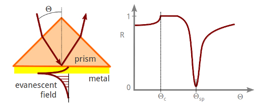
If a thin (~100nm) nobel metal layer (e.g. silver or gold) is evaporated onto the base of the prism, so-called “surface plasmon polaritons”
(propagating electromagnetic waves at the interface of the metal and the dielectric material that is in contact with the metal)
are excited at a distinct resonance frequency, i.e. at a distinct incidence angle of reflection θsp. In other words: at an angle of
incidence slightly greater than the critical angle for total internal reflection θc, light is strongly absorbed.
A study of this absorption leads to an understanding of the behaviour of electrons at the boundary between two media.
Introduction: The nature of electrons makes it difficult to observe their behaviour and interactions directly.
In order to increase our understanding of these fundamental particles it is necessary to observe their actions in exceptional
circumstances, such as the boundary between two materials. In this experiment, the interaction of bound metallic electrons
with polarised laser light at the interface of silver and a dielectric medium is studied and some of the electromagnetic theories underlying
this behaviour are analysed.
In the following experiment, electron excitations are produced in a thin metal film bounded by air. A coating of silver was
evaporated on the edge of a glass prism and laser light was shone through one of the other faces. At certain angles of incidence
the light was able to produce surface plasmons resulting in a noticeable drop in the reflected intensity. Surface plasmons are
short range phenomena, which can be regarded as an enhanced electromagnetic field that propagates along the interface with
high attenuation, and can only be excited by the use of p-polarized light as we will see in the following section.
Simple Theory Consider a charged particle free to oscillate under the influence of a time varying electric field.
The motion of the particle will be small unless the frequency of the field is very close to its resonant frequency.
In electromagnetic terms, a bound electron will interact only weakly with light unless the light has the correct wavelength to excite it,
in which case the energy of the light will be heavily absorbed by the electron. To a human observer it would appear that the material
is kind of transparent to light at many frequencies, but opaque to a narrow range of wavelengths. But the wavelength of light is
related to its momentum, so were it is possible to vary the momentum without varying the frequency, the same effect is observed.
This is exactly what happens when polarised light is incident on a metal film at varying angles.
 But let us start from the beginning and with some basic concepts of solid state physics and electromagnetism. Electromagnetic radiation,
viz. light, consists of orthogonal oscillating electric (E) and magnetic (B) fields transverse to the direction of propagation.
If such a radiation passes through a linear polariser it will be plane polarised, meaning that there will be a well specified plane in which
E or B oscillate (see figure on the left). Now if we consider such a radiation falling at an incedent angle θi
upon a smooth planar interface we have to deal we two important situations.
But let us start from the beginning and with some basic concepts of solid state physics and electromagnetism. Electromagnetic radiation,
viz. light, consists of orthogonal oscillating electric (E) and magnetic (B) fields transverse to the direction of propagation.
If such a radiation passes through a linear polariser it will be plane polarised, meaning that there will be a well specified plane in which
E or B oscillate (see figure on the left). Now if we consider such a radiation falling at an incedent angle θi
upon a smooth planar interface we have to deal we two important situations.
In the first instance the incident radiation has its electric vector in the plane of incidence - the plane perpendicular to the surface
which contains both the incident and reflected wavevector. This is called p-polarised (p from parallel to the plane of incidence).
For such radiation clearly the B-vector has only one component, By, which is tangential to the interface
leading to the term TM-wave (Transverse-Magnetic wave). The E-vector has the components Ez,
which is normal, and Ex, which is tangential to the interface.
In the second case the incident radiation is polarised so that its electric field vector is orthogonal to the plane of incidence. This is called
s-polarised (s from the german senkrecht meaning perpendicular). Here the E-vector has only one component,
Ey, tangential to the interface leading to the term (you guessed it!) TE-wave (Transverse-Electric wave).
The B-vector has the components Bz normal, and Bx tangential to the interface and orthogonal to the Ey
component and the plane of incident.
Any linearly polarised radiation can be readily represented by the sum of these two cases.
 CAUTION! There is no universal convention in this TE and TM naming scheme, and certain authors do refer to light with p-like electric field
as TE and light with s-like electric field as TM. Throughout this webpage I will stick to the above described scheme.
CAUTION! There is no universal convention in this TE and TM naming scheme, and certain authors do refer to light with p-like electric field
as TE and light with s-like electric field as TM. Throughout this webpage I will stick to the above described scheme.
The figure on the right illustrates an electromagnetic wave with p-polarisation hitting a smooth planar interface.
Each component of the electric and magnetic field is labeled using the above described convention with i = incident,
r = reflected and t = transmitted.
And now let us consider that the second medium is a non-magnetic material, meaning that the relative permeability at the
frequency of the incident radiation is unity. What does that mean to the B-part of our electromagnetic radiation? To make it short:
because there is no discontinuity at the interface for that part, we can forget it. Now the behaviour of the radiation at the interface is
only govern by the discontinuity in the dielectric constant viz, the E-field.
There is of course one important simplification in this consideration: Any optical activity in the second medium, that is the property of a material which
allows it to rotate the plane of polarisation of an incident photon even if it is propagating along an axis of symmetry in the system,
is ignored.
We reached the photon-level by now. Just to remember: a photon is an elementary particle, the quantum of light and all other
forms of electromagnetic radiation. Strictly speaking it is the force carrier for the electromagnetic force. Like all elementary particles,
photons are currently best explained by quantum mechanics and will exhibit the so-called wave–particle duality.
However, being a particle the photon has a momentum which is defined as pph = ℏk with k = 2π/λ.
(ℏ is called the reduced Planck constant or Dirac constant. It is equal to the Planck constant h divided by 2π).
In a medium 1 with the refractive index n1 the photons have the pseudomomentum ℏkn1 = ℏki.
When these photons hit the planar interface to medium 2 they impart their momentum in the direction normal to the interface (kz)
and in the direction parallel to it (kx).
Let us look at the reflected wave first: Since ℏ|k1| needs to stay the same in medium 1 unless the photon frequency is changed (meaning |ki| = |kr| in the above figure), and ℏkx1 is conserved for a smooth interface, it follows that krz = -kiz. That is the usual law of reflection at a planar interface.
On the other hand inside the medium 2 the refractive index is n2 and the radiation has a new wavelength
λt = λi /n2 and a new wavevector
kt = n2ki. In this medium the radiation is travelling in a new direction,
keeping kx constant but allowing kz to change. From the figure above we know that
kix = ki sinθ
and ktx = kt sinθ'. Using the relationship
ktx = kix we get
ki sinθ = kt sinθ' or
n1 sinθ = n2 sinθ' which is Snell's law of refraction.
And now consider that the radiation is incident from a high refractive index medium, n1 = ε1½,
on to a low index medium, n2 = ε2½ with n2 < n1
and ε1, ε2 the relative permittivities of medium 1 and medium 2 respectively. Following Snell's law we have:
ε1½ sinθ1 = ε2½ sinθ2
Because n1 / n2 > 1, sinθ2 > sinθ1, the radiation is bent away from the normal.
Thus there must be some value of θ1 less than 90° for which Snell's law gives sinθ2 = 1 or
θ2 = 90° - as seen in the figure on the left. The angle of incidence for which the refracted radiation emerges tangent to the surface is called the
critical angle, or θc.
sinθc = ε2½ / ε1½ = n2 / n1
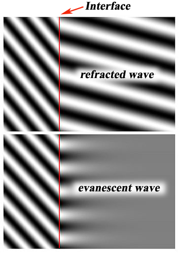
These fields cannot propagate inside medium 2 like normal refracted fields (as seen at the top of the figure on the right),
insted they are spatially decaying, or evanescent fields which oscillate in time at the same frequency as the incident radiation.
These fields are decaying exponentially in intensity (and therefore amplitude since
I ∝ Emax2) in medium 2 in the direction normal to the interface - as seen at the bottom - according to the equation:
I(z) = I0 e-z/d
where I(z) represents the intensity at a perpendicular distance z from the interface and I0 is the intensity at the interface.
The characteristic penetration depth d at λi , the wavelength of the incident light, is given by:
d = λi / 4π (n12 sin2θ - n22)-½.
NOTE! When z is equal d the intensity at this position is I(d) = I0 e-1,
meaning that the intensity has fallen to approx. 0.37 of I0. This is an important value for microwave engineers - the
skin depth δ.
...to be continued....